Thorp S-18 -> T-18

|
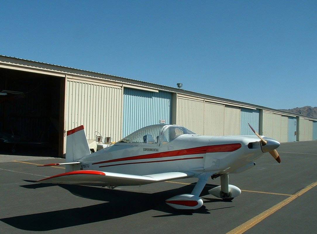
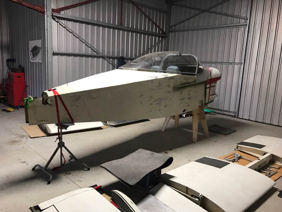
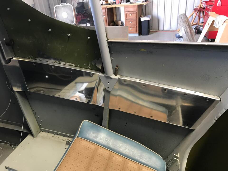
As if I don't have enough to keep me busy, I've decided to start working on a Thorp S-18 as a nice 2-place cross country airplane. Here is a nice example of a well built S-18. It's a Thorp T-18 with a widened fuselage and folding wings with a modified airfoil for better stall behavior.
My initial plan to build an S-18 changed when I purchased a T-18 project in 2017. |
3-4 Jul 2016 (4 hours, total time to date: 4.0 hours)
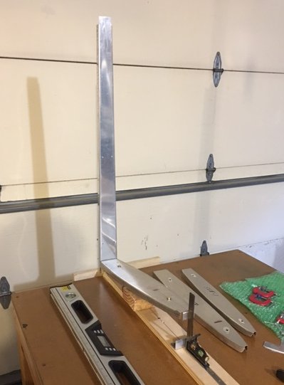
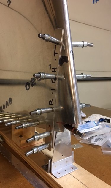
I received the vertical fin kit and inventoried the parts. I studied the plans to verify the requirements for assembly. I found one fairly large error in the plans - one of the fuselage station dimensions had not been converted from the original T-18 plans (the S-18 has been lengthened by 5 inches). The fin beam has been marked from drilling attachment holes for the ribs and attachment holes to the BH. I laid out the remaining holes along the lower section for the doublers (on the web only). I lightly punched the locations and drilled them to #41. I clamped each doubler in place and match drilled the holes in the beam web to #40. One of the doublers ended up with a marginal edge distance (~7/32) at the upper attachment hole. This did not occur for the other doubler, and I soon realized that the doublers were not matched. Instead of using this doubler, I made a new one that was a match to the doubler with a good edge margin for this hole (~9/32). I also installed a small wooden beam above my work table to allow me to hang a plumb bob along the fin to help verify alignment.
8-9 Jul 2016 (6 hours, total time to date: 10.0 hours)

I laid out the fastener locations along the flanges at the lower end of the fin beam. These attach the doublers to the beam. I didn't drill any holes in the flanges where the skin will attach. I cut pieces of 3/4 in. birch plywood to mount the beam to the end of my work table. This includes two spacers to clear the table top overhang, and one strip to fit under the root rib to define the C/L of the airplane. I attached the spacers to the table and laid out the beam on the plywood. I match drilled the #40 holes in the plywood, removed the beam, and drilled out the holes to 1/4 in, (to allow me to insert clecos once the beam was attached). I drilled the 4 beam attachment holes to #13 on my bench press to be sure they were as true as possible. I then progressively drilled out these attachment holes in the beam/doublers to #13, replaced the beam on the plywood and match drilled these to #12 for AN3 bolts. I also cut notches along the upper edge of the plywood on either side of the beam to allow clearance for the fin skin. I then aligned the plywood to the work table and screwed it in place. I used shims as needed to obtain proper vertical alignment. Then, I aligned the plywood strip along what would be the C/L of the A/C, marked the C/L, and screwed it to the table. I marked the location of the attachment holes in the lower rib flange with a line that was visible through the attachment holes in the beam/doublers. The location of this line places the top edge of the root rib according to the plans. I cut two 3/4 inch strips of some scrap 0.032 aluminum and clamped them on either side of the beam and rib to ensure that the rib was properly positioned on the beam. Finally, I rechecked alignment in all directions and match drilled #41 attachment holes through the root rib flange.
10-11 Jul 2016 (4 hours, total time to date: 14.0 hours)
I spent more time than I planned checking and double checking alignment and making a few minor adjustments. I established a reference for WL48.0 above the fin alignment strip to make it easier to measure the location of the forward fin attachment hole. I also established the FS for this attachment hole. Once the lower fin rib is positioned at the 8 degree angle, things should work out, but there is some variability with the location of the rib attachment holes as well as the leading edge flange on the rib. After looking at things closely, I made another minor adjustment to the rib leading edge flange. The vertical BH must also fit inside the joggle in the rib flange. For now, everything looks good.
12-13 Jul 2016 (2 hours, total time to date: 16.0 hours)
I fabricated a wood support to fit under the fin root rib to hold it at the 8 degree incline and provide rigid base to support the other ribs. I also cut some hard wood blocks with a bend line radius, measured the fin spar for the upper flange bend line, clamped the blocks in place and bent the upper flange with a rubber mallet. I then finished the bend with my flange tool to get close to the 8 degree incline.
14-15 Jul 2016 (2 hours, total time to date: 18.0 hours)
I located the lower rib support on the fin alignment strip, drilled two attachment holes at the base of the support, and screwed it securely to the strip. I then drilled an attachment hole through the lower rib, re-aligned the lower rib, and installed a #6 screw through the rib to the lower rib support.
16 Jul 2016 (3 hours, total time to date: 21.0 hours)
I fabricated two rib spacers from some scrap aluminum to hold the center and upper ribs in place for assembly. Before fitting the center rib, I marked the locations for the attachment rivets, and used my fluting tool between the rivet locations to flatten the rib. I then bent another piece of aluminum to attach to the lower end of one of the rib spacers and allow it to be attached through the lower rib at the proper alignment to support the center rib. I then clamped the center rib to the fin spar and match drilled #41 pilot attachment holes through the spar. Once the support was in position, I match drilled two #30 attachment holes through the support to attach the angle to the support. I riveted the angle/support, and replaced the support on the lower rib.
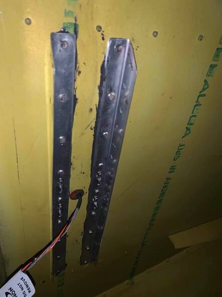
Note: The support shown in this picture is only being used to aid in the alignment/assembly of the fin structure. The supports will be removed prior to final assembly (per plans).
Note: The support shown in this picture is only being used to aid in the alignment/assembly of the fin structure. The supports will be removed prior to final assembly (per plans).
18 Jul 2016 (1 hour, total time to date: 22.0 hours)
I fabricated two angle brackets to attach to each side of the middle fin rib to temporarily attach it to the vertical supports that will hold the ribs in position to fit the skin. I drilled the attachment holes, located the C/L of the middle rib, and drilled the bracket attachment hole to 0.162 in. for a #8 machine screw. I also drilled two, 1/8 in. pilot holes in the brackets the will attach them to the vertical supports. Finally, I attached the brackets to each side of the middle rib with a machine screw.
19 Jul 2016 (2 hours, total time to date: 24.0 hours)

I located the attachment hole for the two angle brackets on the middle rib by aligning the leading edge of the upper bracket along the forward edge of the lower support. I marked the attachment hole through the C/L of the middle rib. I then attached the brackets to this rib with a #8 machine screw. I clamped the lower bracket to the lower support and aligned the middle rib by adjusting the fit of this bracket on the support. It took a little while to do this, and I ended up removing the rib a few times to trim the bracket flanges to allow sufficient clearance with the rib flange. Once I had it aligned, I match drilled the attachment holes through the lower support, re-checked alignment, removed the rib (again), and riveted the lower bracket to the lower support.
20-21 Jul 2016 (3 hours, total time to date: 27.0 hours)
I clamped the upper support to the upper bracket on the middle rib. I checked the vertical alignment and match drilled the attachment holes through the support. I riveted these holes and replaced the upper rib to check the overall dimensions per the plans. I line along the leading edge of the middle and upper ribs should fall 2 inches in front of the lower rip tip. I needed to trim the aft end of the upper rib flanges to allow the proper fit. I also checked the upper hinge fitting to be sure the hinge would be 2 inches aft of the fin spar web. I aligned the upper hinge fitting with the C/L of the upper rib. This was definitely one of those measure 3 or 4 times kind of situations. I clamped it in place, replaced the upper rib, and checked the dimensions one last time. Finally, I match drilled the attachment holes through the fitting and the upper rib.
22-23 Jul 2016 (4 hours, total time to date: 31.0 hours)
|
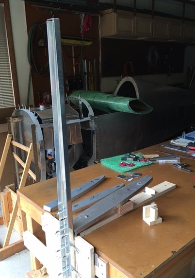
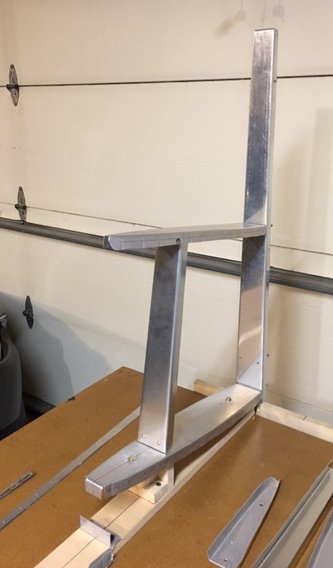
I decided to add a fifth attachment hole on the C/L of the hinge bracket and the upper rib. I wanted to be more confident that the fitting would not move with clecos installed only on the front two holes of the bracket as I match drilled the aft holes through the spar tab. I had to contend with the existing aft rib tooling hole and be careful to have clearance with the spar. I was able to maintain a good hole spacing with the tooling hole in the process, approx. 0.5 inches. With the upper hinge fitting on the upper rib, I started work to align the upper rib on the spar. This was more involved that the other ribs since the hinge needs to be 2 inches behind the spar web, and I was as careful as possible to keep the C/L true. It was not easy to measure the 2 inches to the C/L of the hinge, so I decided to make an angle bracket with a hole 2 inches from the outside of the angle that could be clamped on the C/L of the spar. I bent a piece of 0.050 thick aluminum to fit inside the spar. I set up a drilling guide on my bench drill press to control the 2 inch distance, and drilled a pilot hole on the C/L of the bracket. I then progressively drilled the hole to 7/16 (to match the hole in the hinge bracket. I then clamped the new bracket approx. .75 inches under the hinge fitting (just enough to provide clearance with the clamps I was using to hold the upper rib on the spar. I then made the necessary adjustments to allow the shank of a 7/16 drill bit to slip through the fitting and bracket. I could then use a sight line to my plumb bob to get things lined up. This took a few iterations to get where I thought I was as close as I was going to get. I then match drilled the aft two attachment holes through the fitting/rib/spar tab. Then, I went to work on the front rib support attachment. I made an attachment bracket and located the attachment hole on the rib. I drilled/reamed this hole out to 0.162 in the rib and bracket, drilled a #41 pilot hole on the other leg of the bracket, and attached the rib to the bracket with a #8 machine screw. I replaced the rib and clamped the bracket to the front support. I also checked the angle of the upper rib to verify 8 degrees and also checked to be sure it was parallel to the lower rib. I made the final adjustments to the upper rib to the front support, re-clamped it, and match drilled a #40 holes through the bracket/support. As can be seen in the photo, the upper support is off C/L a bit, but that does not matter. It's only there to hold the upper rib until I can get the skin fitted.
|
25 Jul 2016 (1 hour, total time to date: 32.0 hours)
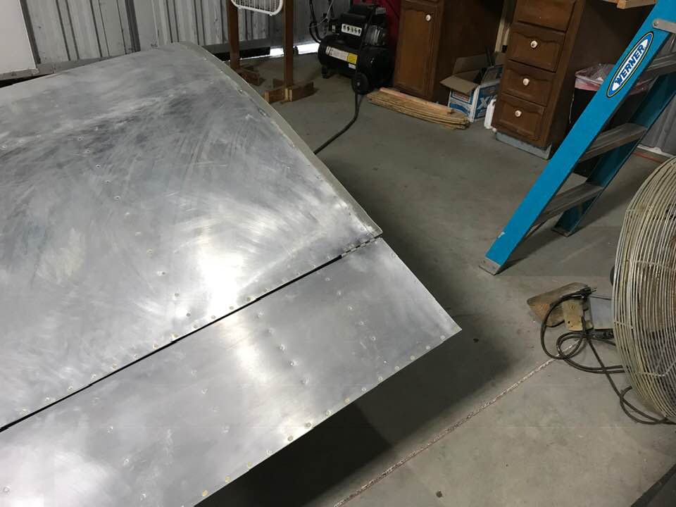
I unpacked the fin skin and laid out a towel on my work table to protect the skin. I clamped the aft edges together on either side of a 1x2 and used a 2x4 wrapped with a towel to form the leading edge bend in the skin. It took several iterations, but it turned out well. It is now ready to fit on the frame.
26 Jan 2016 (3 hours, total time to date: 35.0 hours)
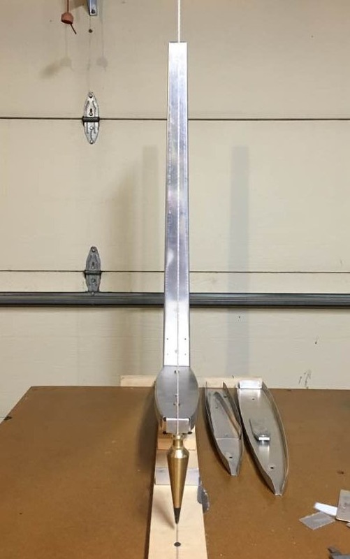
Started work fitting the fin skin on the frame. I used some wood clamps with internal rubberized foam to help hold the skin and clamped the edges as needed. I carefully positioned the skin and double checked the alignment and dimensions. I laid out the rivet line along the upper rib and started at the spar working forward. I continually checked the alignment with a plumb bob as I drilled/clecoed each hole.
27 Jul 2016 (1 hour, total time to date: 36.0 hours)
I continued work attaching the fin skin to the frame. Before proceeding, I removed the skin to measure the distance between the rivet line of the top rib and the rivet line of the middle rib to allow me to draw the rivet line for the middle rib on the skin. I replaced the skin, and resumed drilling the skin attachment holes along the spar flange.
28-31 Jul 2016 (6 Hours, total time to date: 42.0 hours)
I drilled pilot attachment holes (#40) along the spar flange down to the middle rib. Then, I proceeded along the middle rib on each side. To locate the rivet line, I cut a two inch wide, 16 inch long strip of aluminum sheet with two #40 holes on the top to span two attachment holes in the upper rib. I removed the fin skin to cleco the strip on the upper rib. When clecoed to any two holes in the upper rib, I marked the mid rib rivet line on the strip. Fortunately, the two rivet lines were parallel, so the measurement was the same along the rivet line. I was then able to replace the skin, cleco the strip to the fin and mark the mid rib rivet line on the skin. I fabricated more drilling guides to keep the attachment hole spacing consistent and straight (also to prevent the drill from walking). I worked my way forward along the mid rib, then resumed drilling attachment holes along the lower end of the fin spar web. I continued to check vertical alignment as I traveled down the spar. By the time I was past the mid rib, the fin was pretty well locked in place. Once I finished the holes along the spar, I started work along the lower rib. I fabricated a hole duplicator with a 0.062 spacer to allow it to slide around the skin/rib flange. I drilled two holes in this tool - one is 0.25 in. below the top of the locator and the other is 5/16 in. below the top. When the locator is pressed against the rib from below, I could mark the attachment hole location on the skin. I decided to use the 5/16 distance to be consistent with the other rib attachment holes. It provides a little more space and makes it easier to dimple the ribs. Also, it allows some room for error :-). I drilled up to approx. 1+ inches from the forward attachment point for the vertical fin BH. This keeps the skin tight against the rib near this attachment and allows plenty of spacing for the rivet that will tie the BH and rib flanges at this point. It's not clear in this picture, but I didn't change the hole spacing on the lower portion of the fin, I just clecoed every other hole.
1 Aug 2016 (1 hour, total time to date: 43.0 hours)
I marked the lower skin leading edge for the notch required to access the forward fin attach bolt. I taped off the area, and used a cut-off wheel to make the initial cuts. I then used a 1/4 in. drum sander to round the corners, and a 0.5 in. drum sander to smooth the edges. I finished the edges with emery paper and scotch brite. Then, I made a test fit of the vertical BH, and temporarily clamped it in place.
5-6 Oct 2016 (4 hours, total time to date: 47.0 hours)
I removed the fin skin and fabricated a drilling guide to mount to the fin jig for the forward fin attach hole through the vertical BH and the root rib flange. I also fabricated drilling guides to attach to the left and right flanges of the vertical BH to locate the attachment holes. I omitted the BH flange holes at the rib flange because I want to measure those more carefully after I have the BH clecoed in place. The edge distance will be very close for the rib flange due to the location of the joggle on each side. Finally, I replaced the skin, BH, and mounted the forward fin attachment drilling guide on the fin jig.
6-7 Oct 2016 (2 hours, total time to date: 49.0 hours)
I made a 0.025 thick spacers to fit between the vertical BH and drilling guides to allow the drilling guides to fit flush against the fin skin. The fact that the vertical BH was made to extend below the skin works very well for to provide a reference and attachment point for the drilling guide. I will trim it off later.
I match drilled the forward fin attachment hole through the drilling guide attached to the fin jig to 1/8 inch, and match drilled the vertical BH holes to #40 through the other guides. I removed the BH and verified the hole locations. A few are a little close to the BH web, so I will walk them out slightly as I drill them out to 1/8 in. for dimpling.
I match drilled the forward fin attachment hole through the drilling guide attached to the fin jig to 1/8 inch, and match drilled the vertical BH holes to #40 through the other guides. I removed the BH and verified the hole locations. A few are a little close to the BH web, so I will walk them out slightly as I drill them out to 1/8 in. for dimpling.
8-9 Oct 2016 (4 hours, total time to date: 53.0 hours)
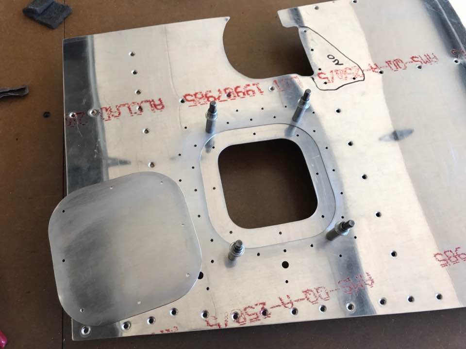
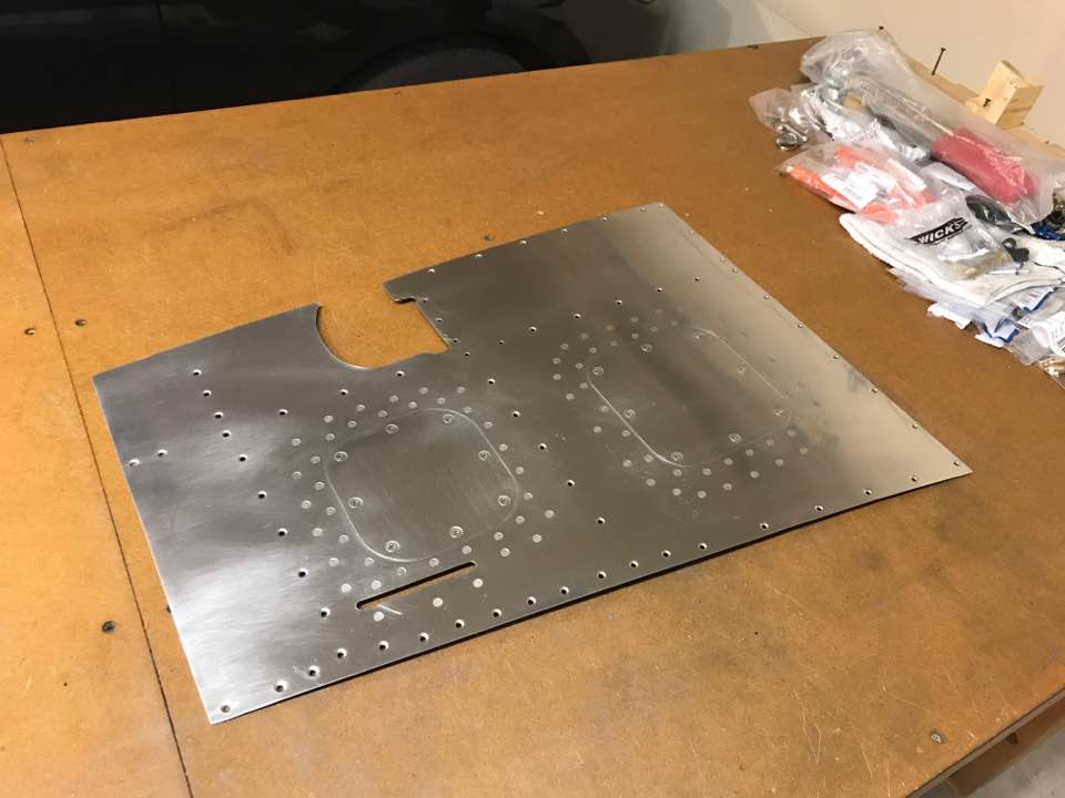
I located the vertical BH attachment holes along the lower rib flange and drilled #40 pilot holes with a drilling guide. I checked the edge distance on the rib flange and walked the left hole slightly inward while drilling both holes out to 1/8 in. I then double checked the forward fin attachment hole to verify that it was on the C/L and drilled it out to a "D" and reamed it to 0.2495. Finally, I drilled all of the fin rivet holes to 1/8 inch for later dimpling.
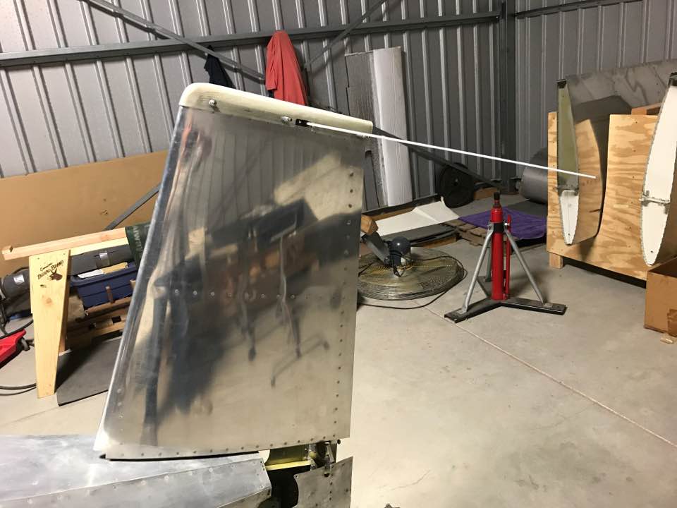
17 Jan 2017 (1 hour, total time to date: 54.0 hours)

I cut two strips of 0.025 thick 2024-T3 to serve as attachment strips for the vertical tail tip cover. I want to install a NAV antenna, so I think it is a better alternative to the plans method of installing the fiberglass tip. I will need to trim the tip to allow the base of the antenna to fit, so I'll need a way to secure the tip on either side of this cut-out. I match-drilled the strips through the fin skin (off of the frame), then replaced the parts. To account for the skin curvature when I match-drilled the holes, I cut wood spacers to hold the upper edge of the skin in the approximate curvature that it has on the frame. As can be seen in the photo, I need to trim the strips. I made them a little oversized since it's always easier to take some off.
March 2017
|
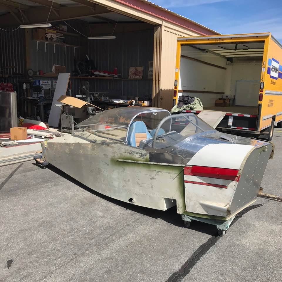
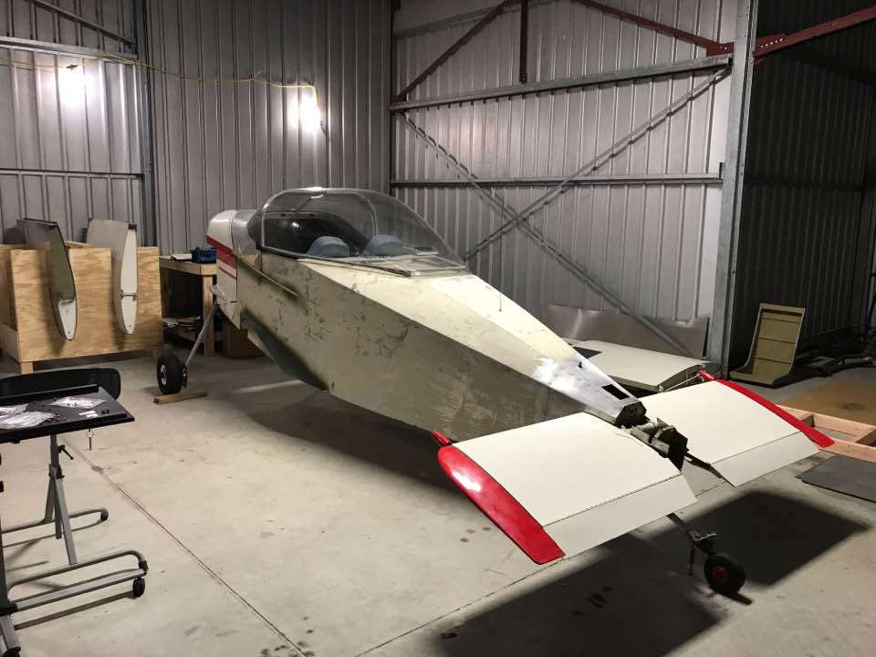
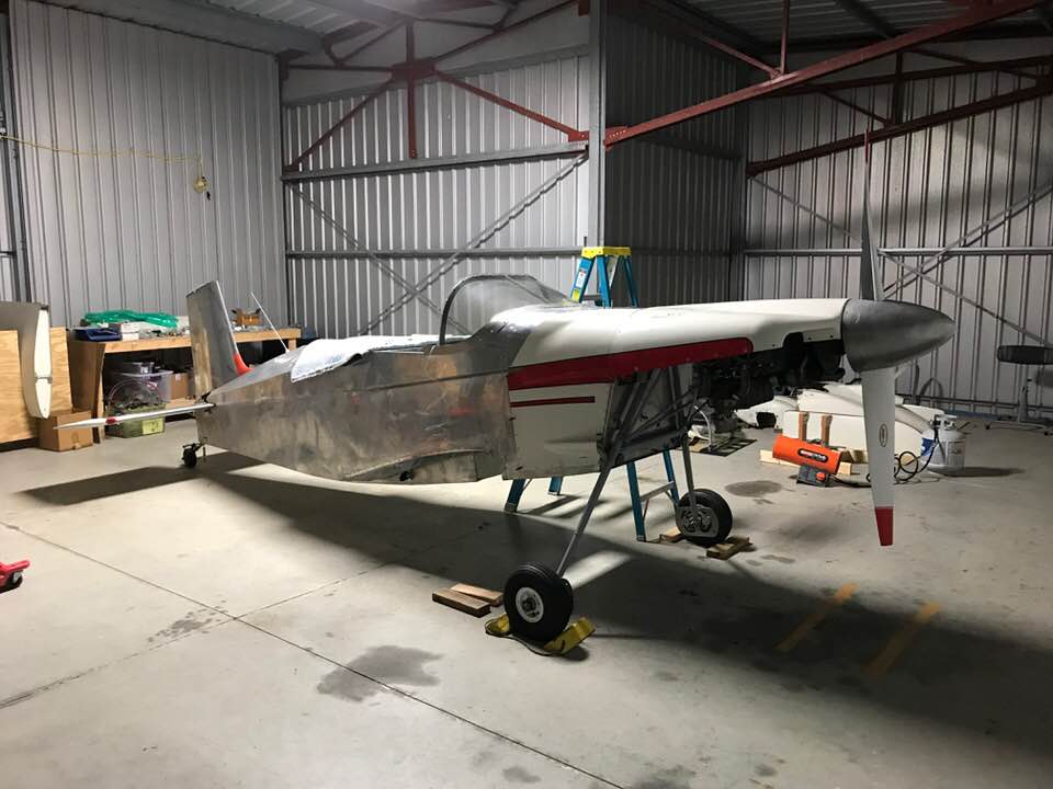
I decided to buy a T-18 that had was in pieces after a major fuel tank leak. The previous owner decided to sell the airplane and it gave me the opportunity to buy a registered T-18 at a great price. Jasson Czaika went with me to Apple Valley, CA to pick it up and truck it back home to Ohio. The picture on the left was the before picture.
The T-18 is not quite as wide in the cockpit (38 vs 40 inches), doesn't have folding wings, and the airfoil is less forgiving. However, it was a great deal, and I need to have a two place airplane for trips with Beth. |
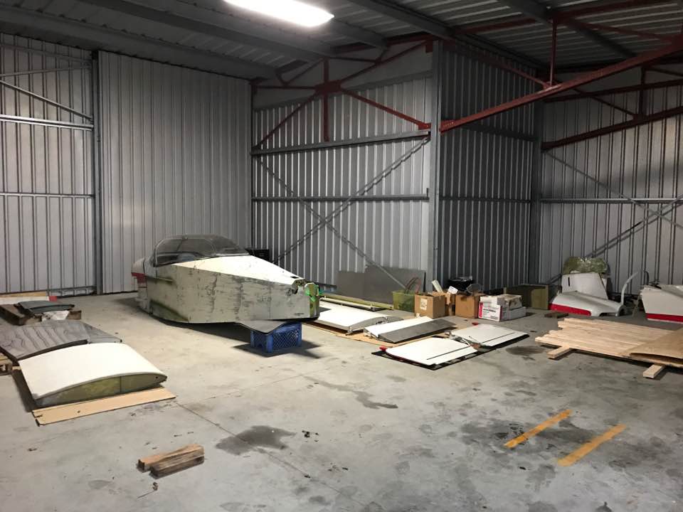
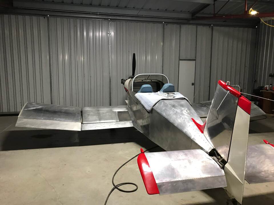
Home in my hangar
Got the fuselage up in supports
There was no bolster for the tail wheel spring, so I ended up making my own reinforcement system to distribute the landing loads between the aft two BHs.
Attached the main landing gear frame.
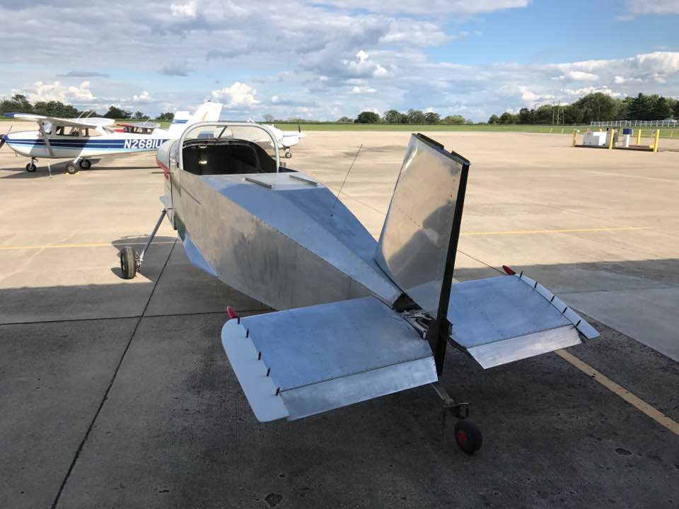
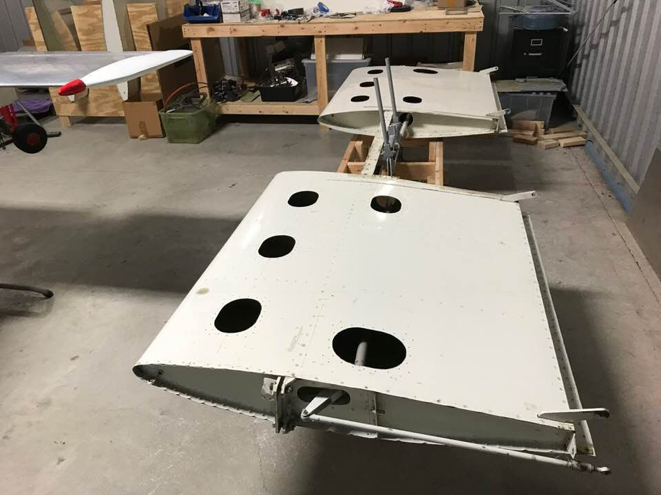
Installed the wheels/tubes/tires/brakes, and test fit the horizontal stabilizer.
The old right wing fairing was cracked, so I made a new one, installed the center wing, and attached the new fairing.
Since I had the center wing on the airplane, I decided to test fit the walking beam, control stick, and made some airplane noises.
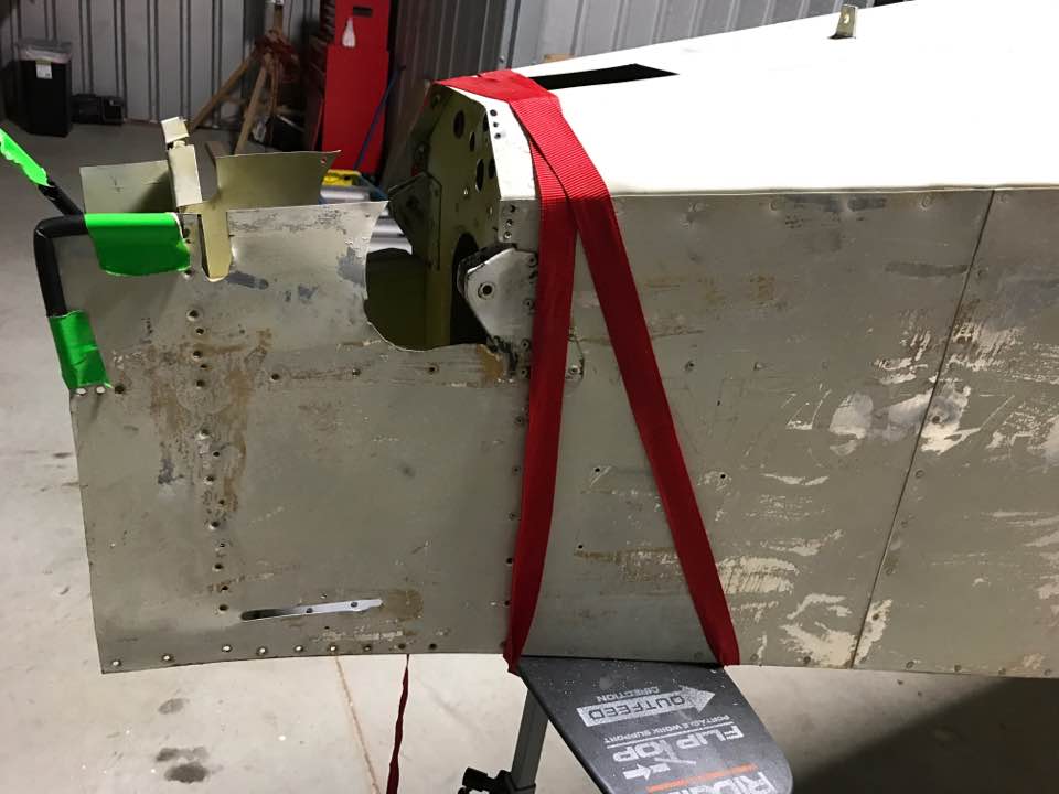
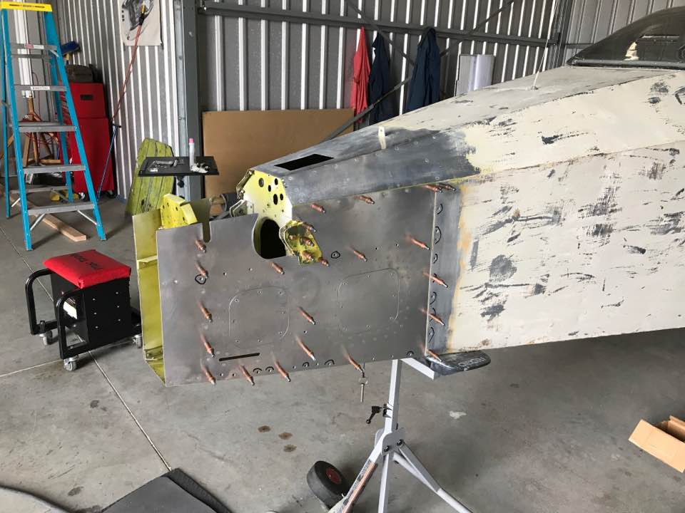
This was a bit of an issue. The original builder wasn't a structures guy, and I couldn't live with this condition on the aft right skin. I drilled out the rivets to remove the old skin.
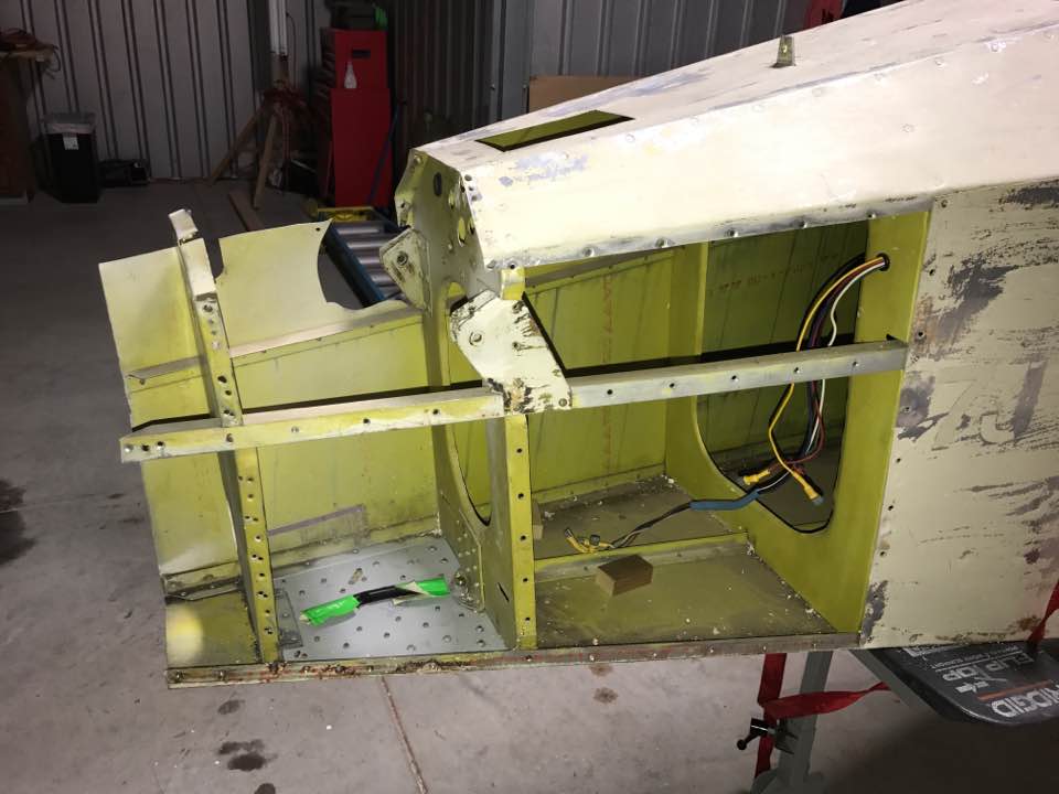
I made new doublers for the aft BH and cut the old flange off of the BH.
Installed the doublers on the BH.
Fabricated a new aft skin with access panels.
Installed the new skin.
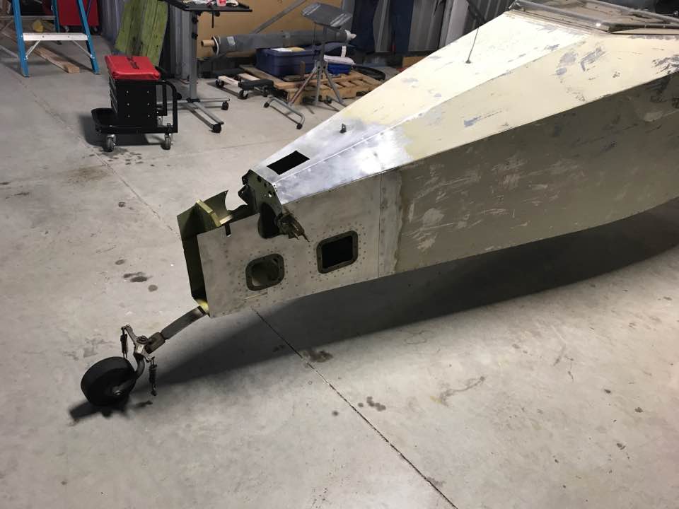
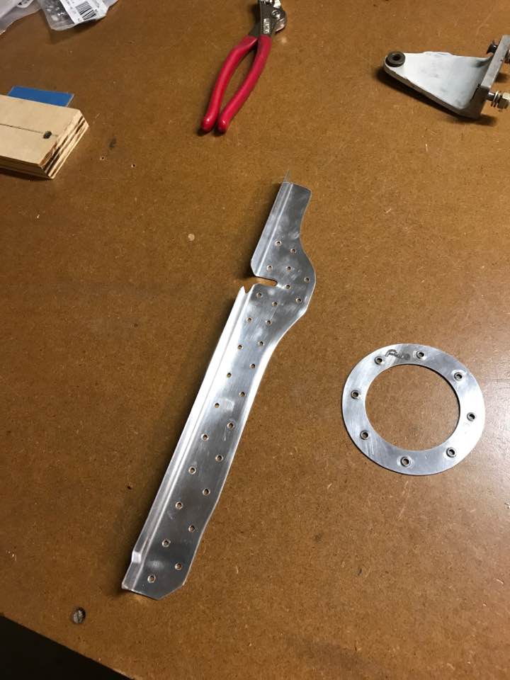
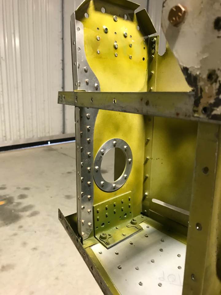
Found some cracks in this BH. No doubt a result of no bolster for the tail wheel spring. I fabricated more doublers to restore the integrity of this BH.
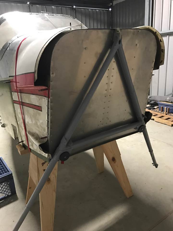
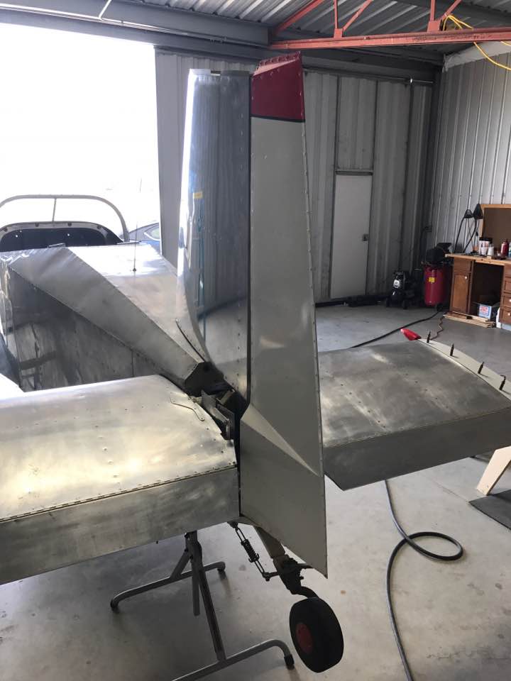
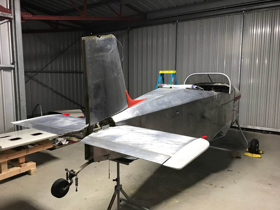
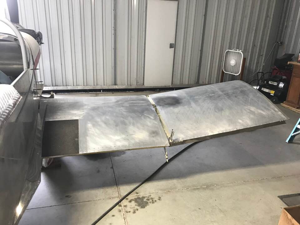
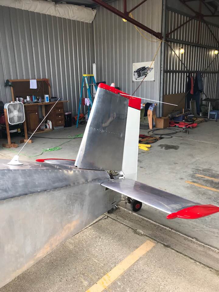
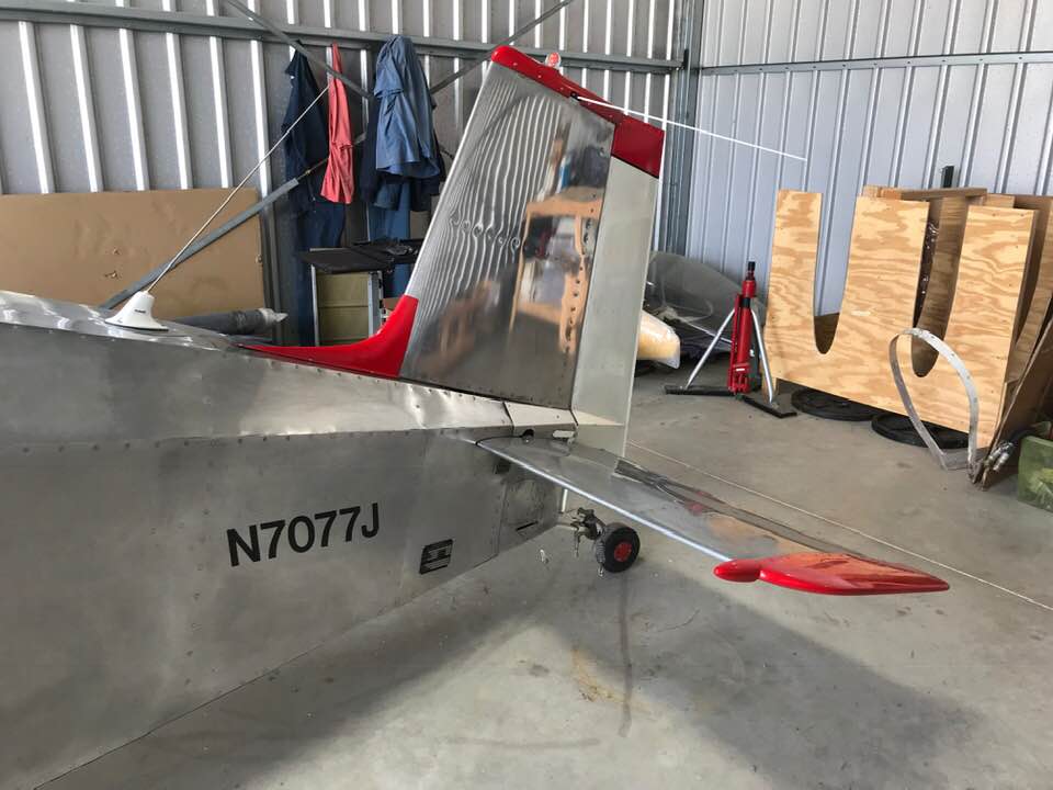
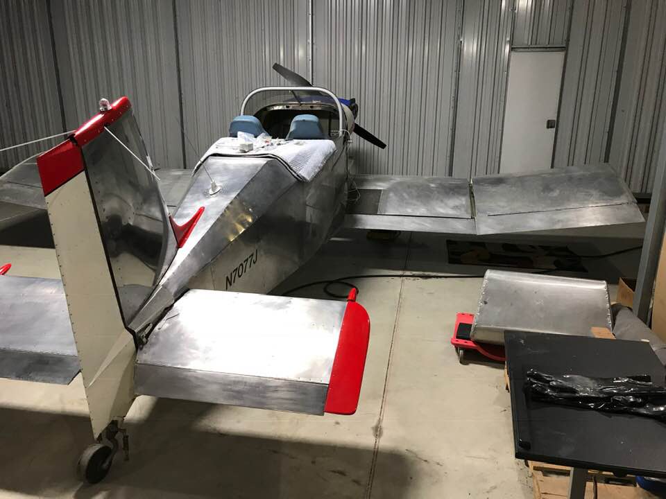
Replaced the horizontal stabilizer and finished up the new vertical fin. I wanted to make sure everything fit correctly.
Finished up the fin I was building for an S-18 and included attachment for a NAV antenna and a pass-through for tail light wiring.

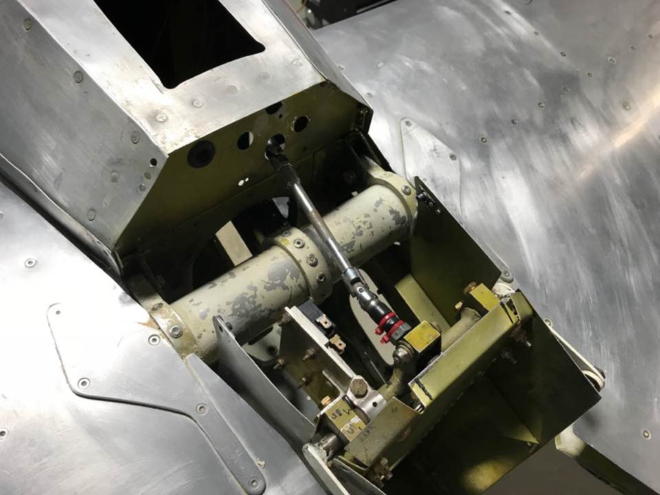
Test fit the electric trim motor and drive shaft.
Test fit the new vertical fin with the old elevator. Perfect fit.
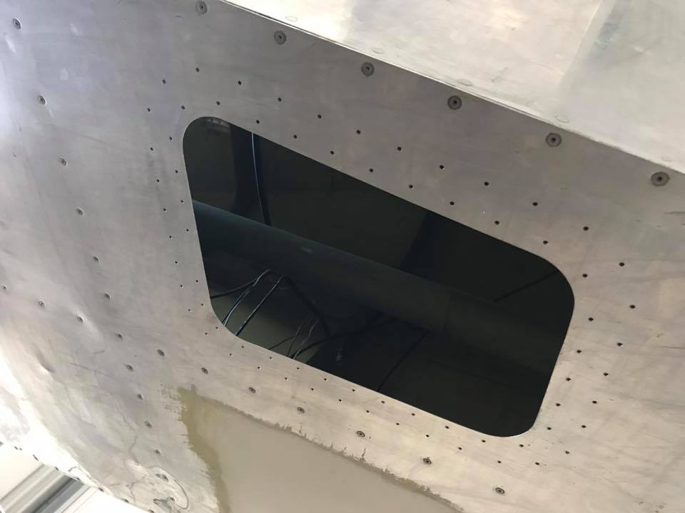
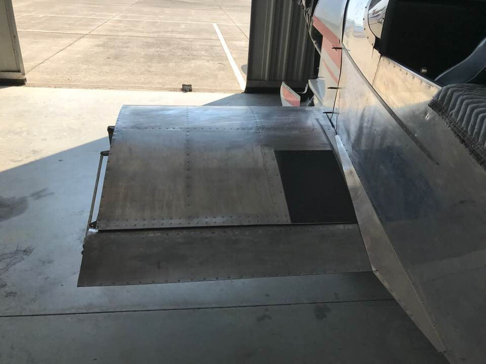
Adding an access panel to the bottom fuselage.
Sep 2017
Finishing up the fuselage paint removal.
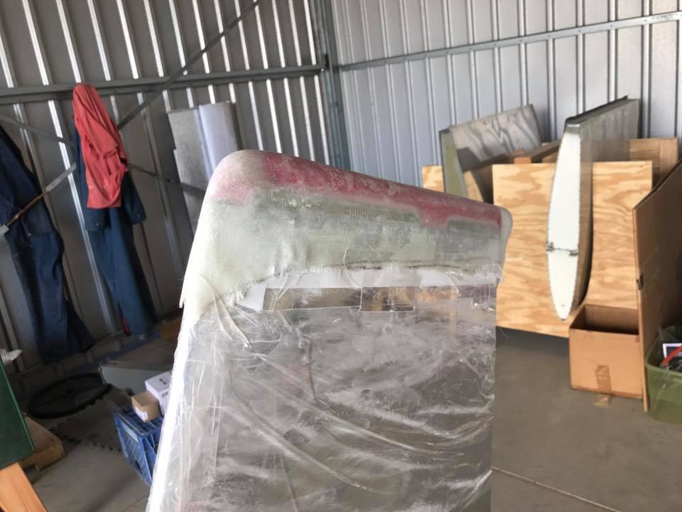
Making a new fin tip.
Test fitting the NAV antenna.
Dec 2017
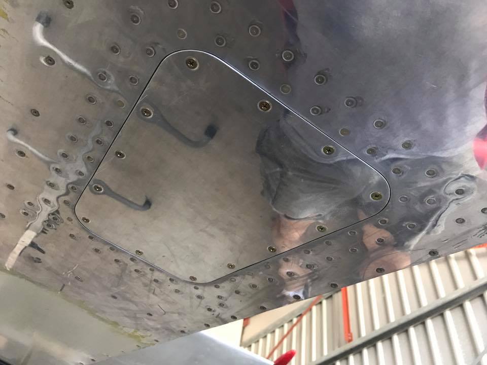
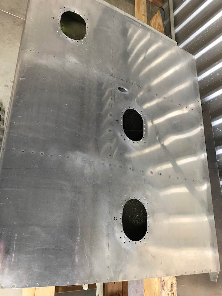
Cut out access panels in the bottom, center wing. I need these to run fuel transfer hoses from the outboard wings, running new pitot lines, and to make any adjustments to the aileron push/pull tubes.
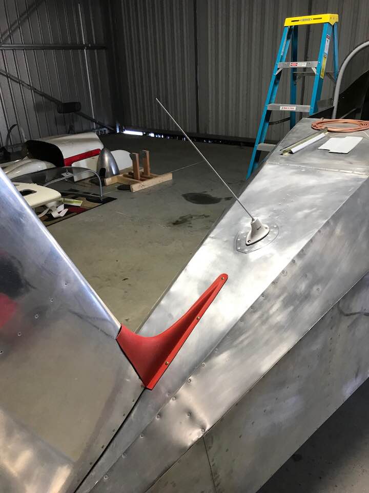
Running the tail light wires, NAV coax, and fitting the fin fairing.
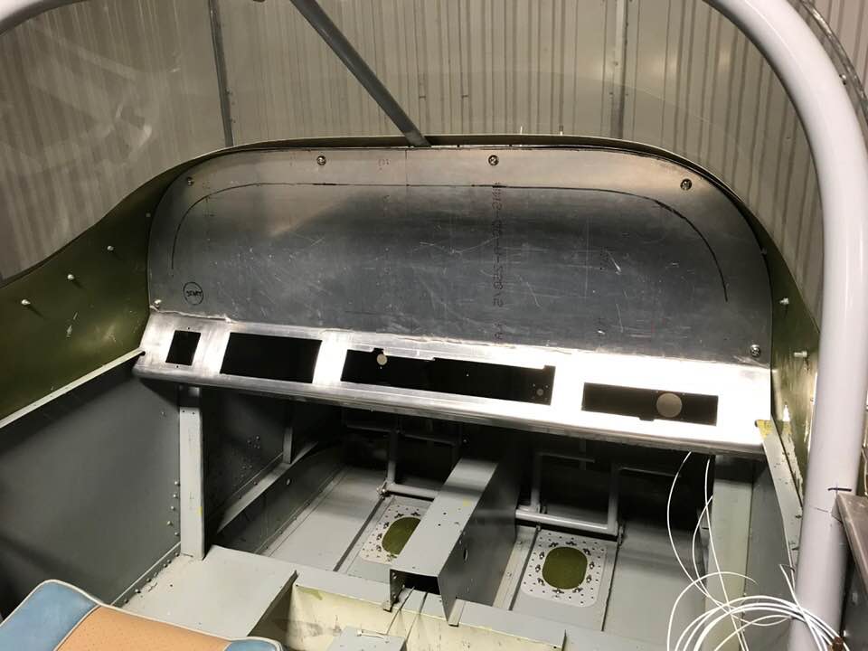
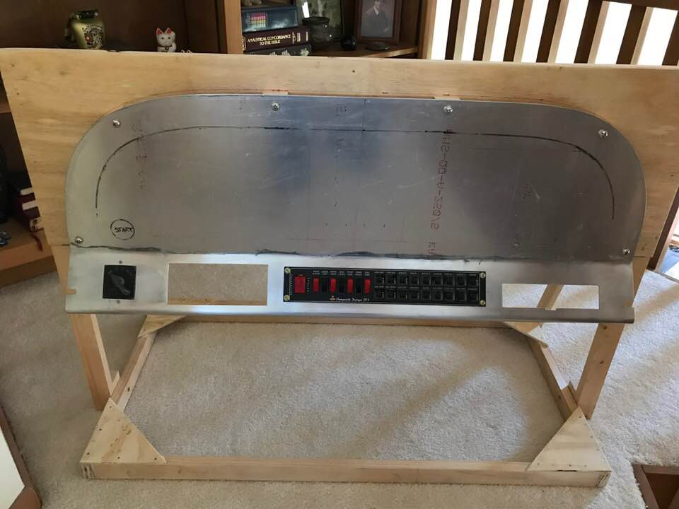
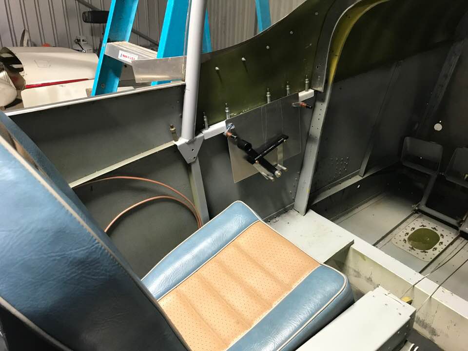
Working on the instrument panel cutouts.
Main switch panel and mag switch. The switch panel should save me some time down the road.
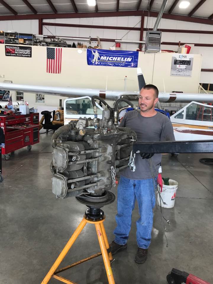
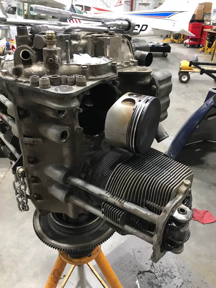
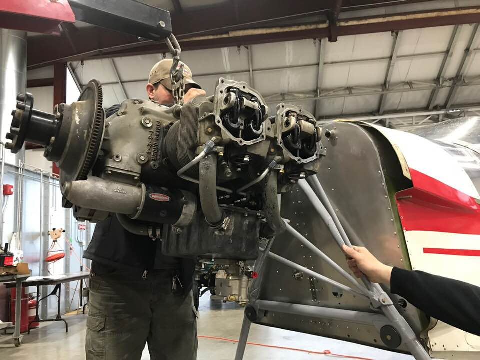
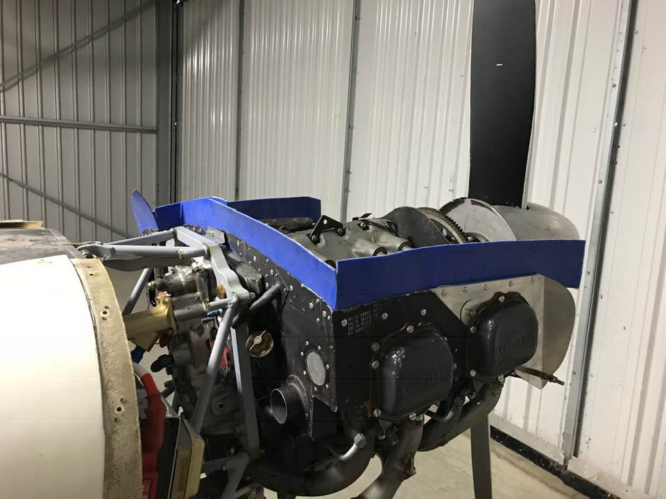
Jasson helping me get the engine cleaned up and ready for him to inspect. He scoped the engine, removed cylinder #4 to check something he saw (turned out to be some carbon deposit), and looked things oven on the inside. Very little wear on all of the contact surfaces. I cleaned things up, Jasson ordered new gaskets, etc., and put it back together.
Dan Jansen really helped me by crawling in the tail cone to buck the nut plate rivets for the fin fairing, and later helped me install the new COM antenna with an external doubler. I had to work around the existing stiffener channel between the two BHs.
April 3, 2018
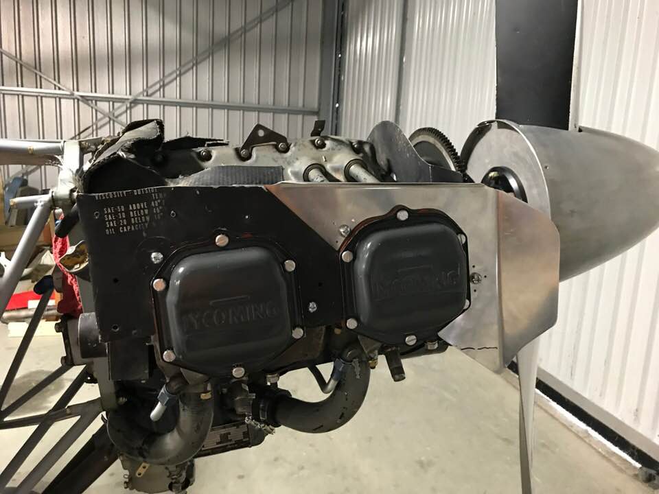
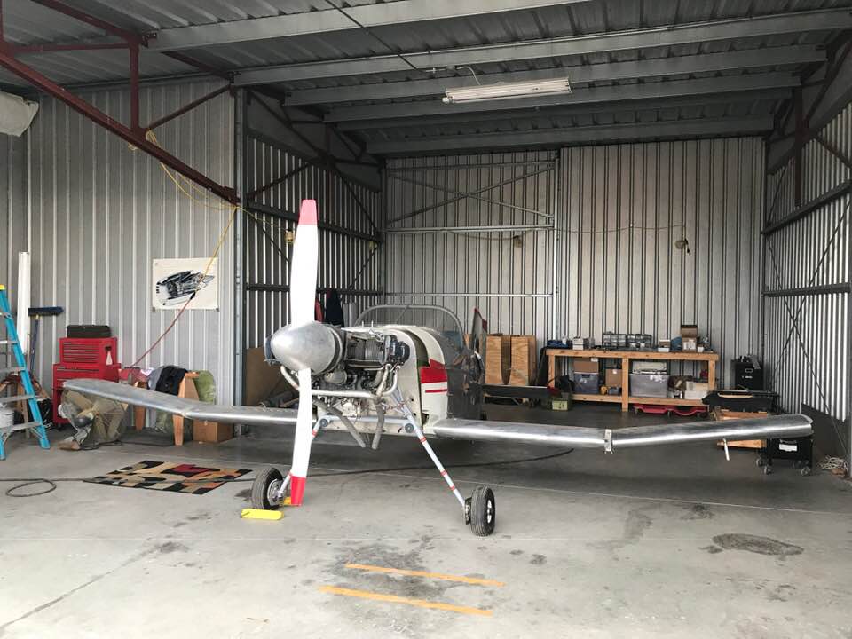
Very big day! Installing the engine.
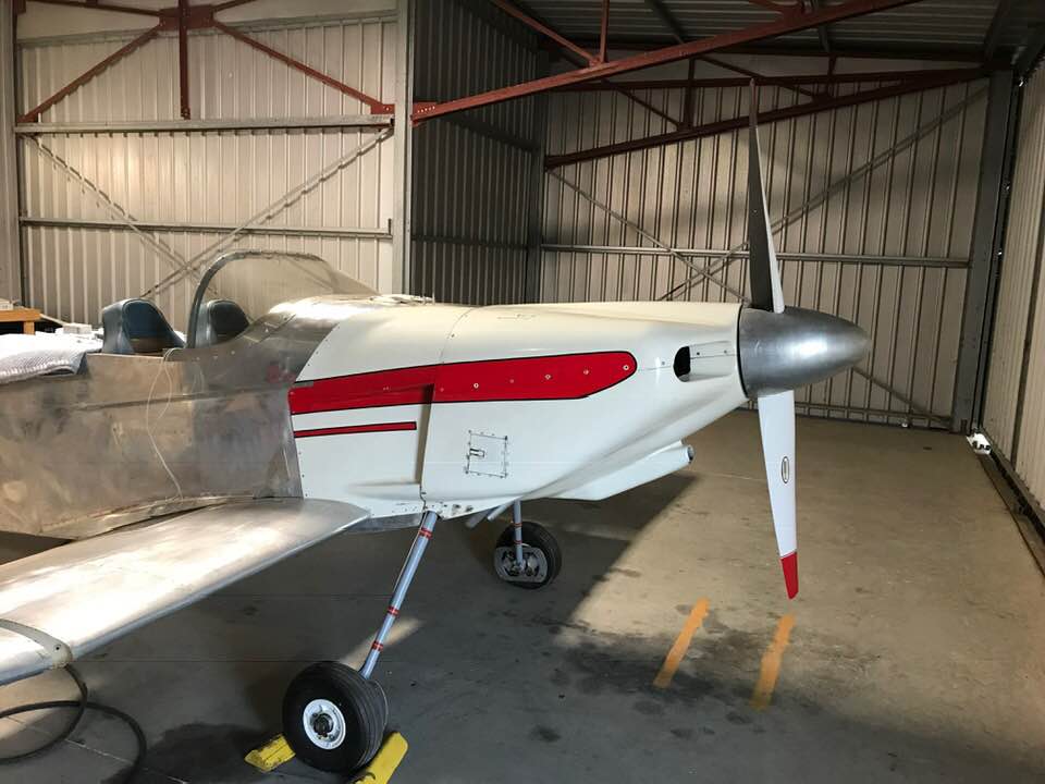
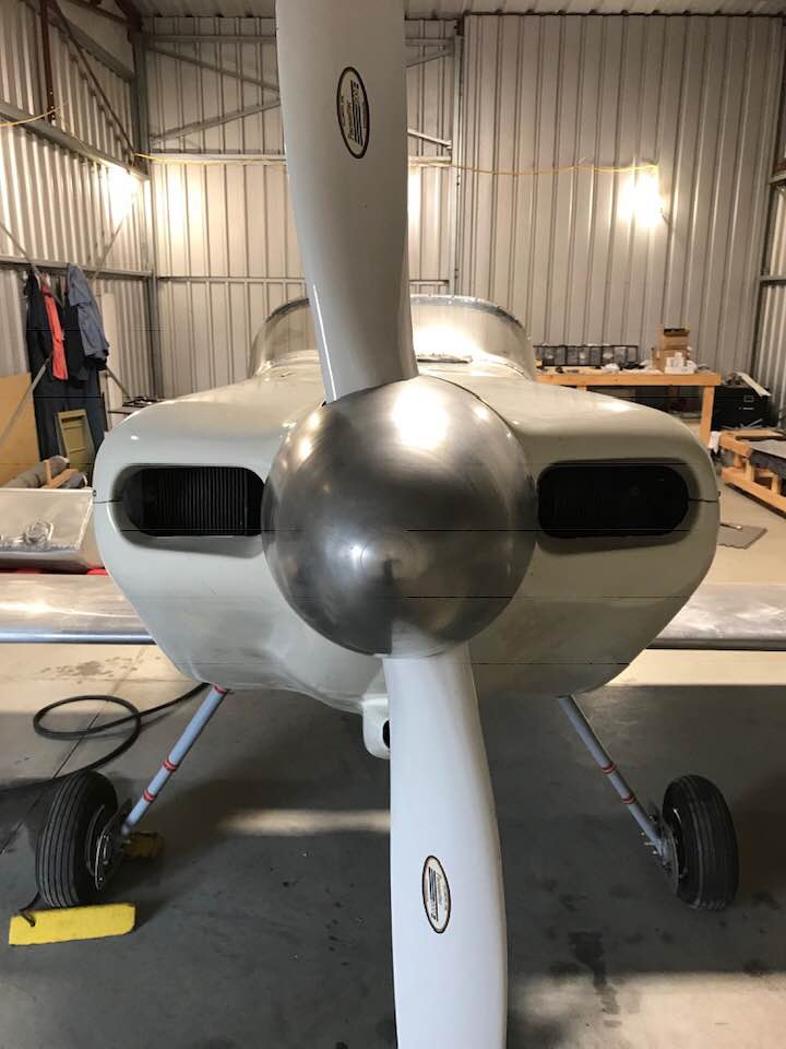
Temporarily installed the prop/spinner to check the cowling fit. Looks great so far...
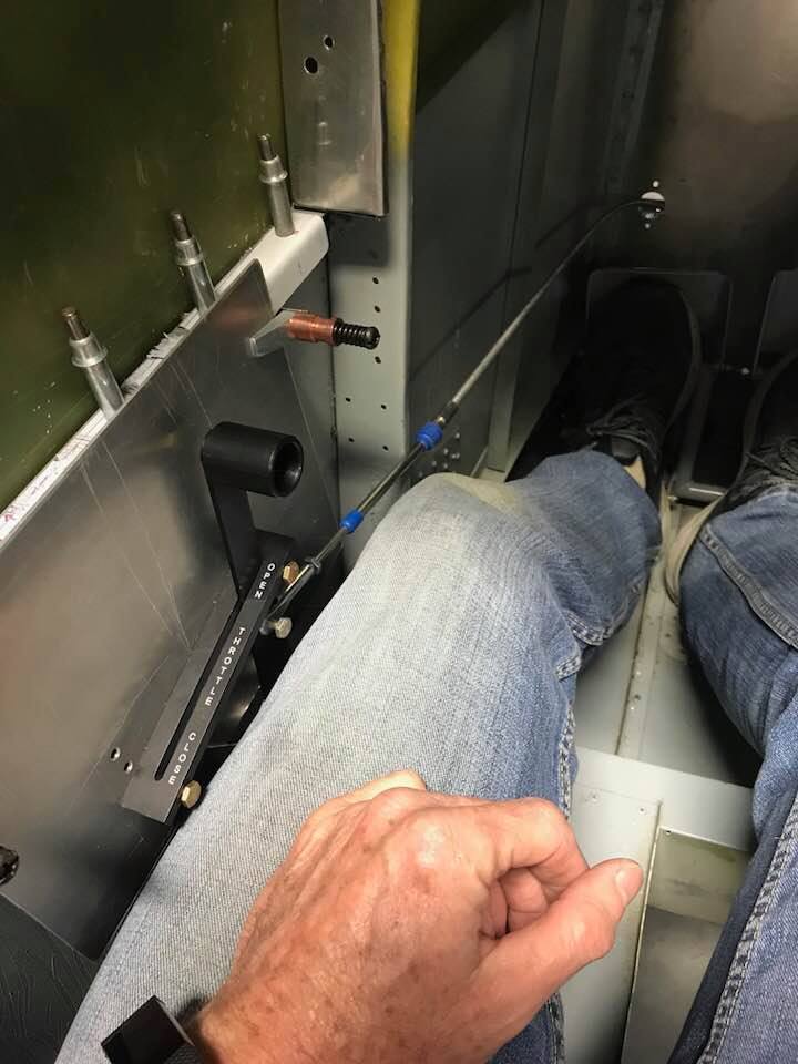
Working out the installation details for the throttle quadrant.
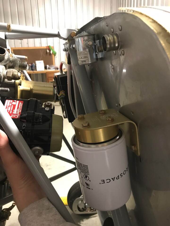
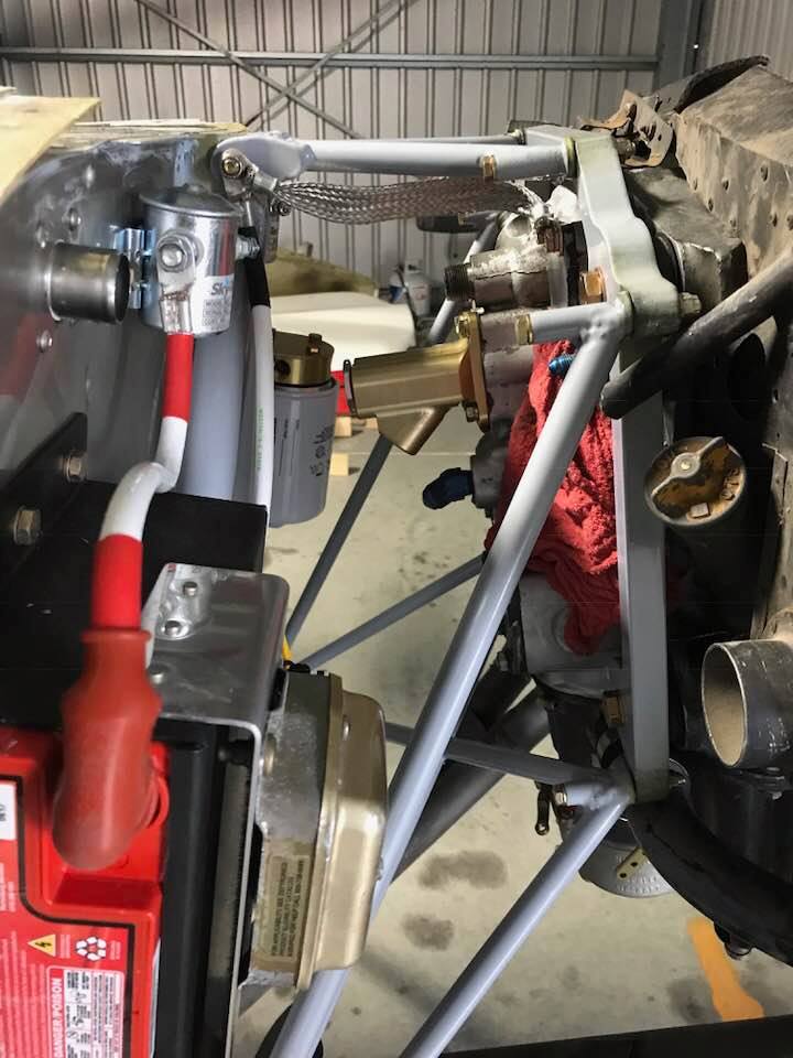
Dan helped me again - installing the remote oil filter. Also, as an afterthought, I checked the clearance for the left mag. Whew! that could have been bad news. Not in this picture, but I also fabricated 0.032 angle stiffeners and installed them to stiffen up the firewall around the filter bracket and at the gascolater with help from Neal Tudor to buck the rivets.
May 2018
Doing some wiring.
Replacing some engine baffle pieces. Some of the original parts had very thin cross-section that had cracked or severed completely. On the new piece below, I added a flange to solve this problem, add a little stiffness, and still give the required clearance for the upper cowling. The biggest challenge here was bending the slip connection with the aft piece to match correctly. I used a strip of 0.062 with a rounded edge inside the bend for the 0.032 material. That gave me a reasonable bend radius for the slip joint, and I used fluting pliers to finish and get a nice fit at the connection.
July 2018
Installing the primer valve
Aug 2018
Finally finishing the center wing access panels

Removing the paint using Rustoleum Aircraft Paint Remover.
Fabricated a throttle/mixture control bracket from stainless steel. Similar to what I've seen on-line from Vans.
Sep 2018
Installed the Center Wing
Installed inspection panels on the right wing and started work fitting it to the center wing.
Installing access panels and a heated pitot in the left wing.
Oct 2018
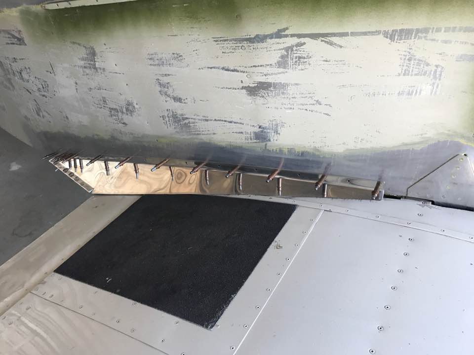
Painted the fin tip and stabilator tips and installed the tail light.
Fitting the control surfaces
Tail Number and Data Plate
Nov 2018
Installed the baffle seals
Started working with the cowling
The right outer hinge was misaligned. I had to drill it out and Jasson helped me rivet a new hinge half in place.
I had to trim the nose of the right flap slightly for clearance, then reinstalled it to check for spacing between the flaps and ailerons before drilling out the rear spar attachments on the outer wings.
Dec 2018
Didn't get a lot done on the Thorp this month. I spent what time I had doing some wiring work. I ran #8 main power wires through the left upper pass through to be connected to my switch panel on the IP. I mounted the ammeter shunt to the firewall, ran a #8 wire from the alternator to the shunt, and from the shunt to the powered side of the starter solenoid. I connected diodes to the master and starter solenoids to protect the switches from arcing due to any back flow of current when the switches are turned off. I also ran #18 wire for the master and starter switch to the cockpit.
Jan 2019
I went back to work on fitting the cowling. When I tried to fit the cowling in November, it was clear that the fiberglass side panels needed to be moved to allow the cowling to fit properly to the spinner now that I have installed new motor mounts. Unfortunately, this means that I will need to fill at least some of the #30 fastener holes in the side skins. Dan Jansen helped me re-install the cowling to re-check the proper position. It was necessary to trim the fiberglass side panel cut-outs for the external stiffening strips. The forward holes were at the edge of the forward firewall flange, so I decided to use these holes as-is and drill new holes through the fiberglass. The aft holes could be filled and new holes could be drilled through the fiberglass. I'll just need to patch and re-paint the old forward holes in the fiberglass. Dan helped me dimple and fill the aft holes with NAS -4 rivets. We replaced the side panels and cowling and adjusted the position to fit properly. I then drilled the new holes in the skin and fiberglass to hold the cowling in place.
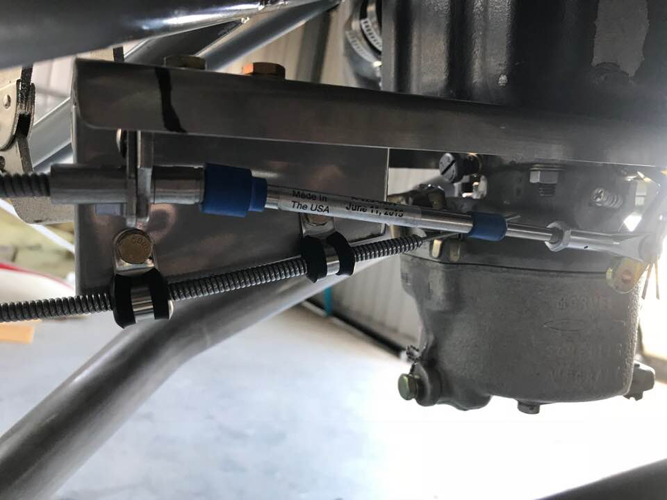
I installed the oil line fittings in the remote filter adapter and fabricated new oil lines for the cooler and remote oil filter. I discovered that the engine has a spring loaded plunger installed where the old oil screen fitting was installed. I'll have to remove it to allow the use of a vernatherm in the new fitting.

Feb 2019
Continued working on the oil hoses. I removed the oil plug and plunger that was blocking the new vernatherm. I replaced the plug and safety wired it. I also safety wired the bolts on the new remote oil filter. Jasson helped me do a pressure check on my new oil hoses. We took them up to nearly 400 psi without any indication of a leak. I installed the hoses on the engine/oil filter/oil cooler.

I also started work on the fuel tank. There are a few things I want to check before I can install the tank. In addition, I need to finish the wiring work through the firewall before I can install it, so now is a good time to make sure the tank doesn't leak. Skeeter assured me that he checked the tank, but I want to double check myself. I don't have an air pressure regulator that can handle the low pressure needed to safely check the tank. I opted for a low tech approach. I used a balloon on a rubber hose and brushed soapy water over the joints. No leaks detected!

Mar 2019
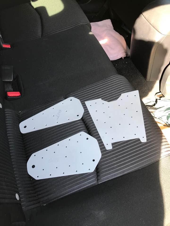
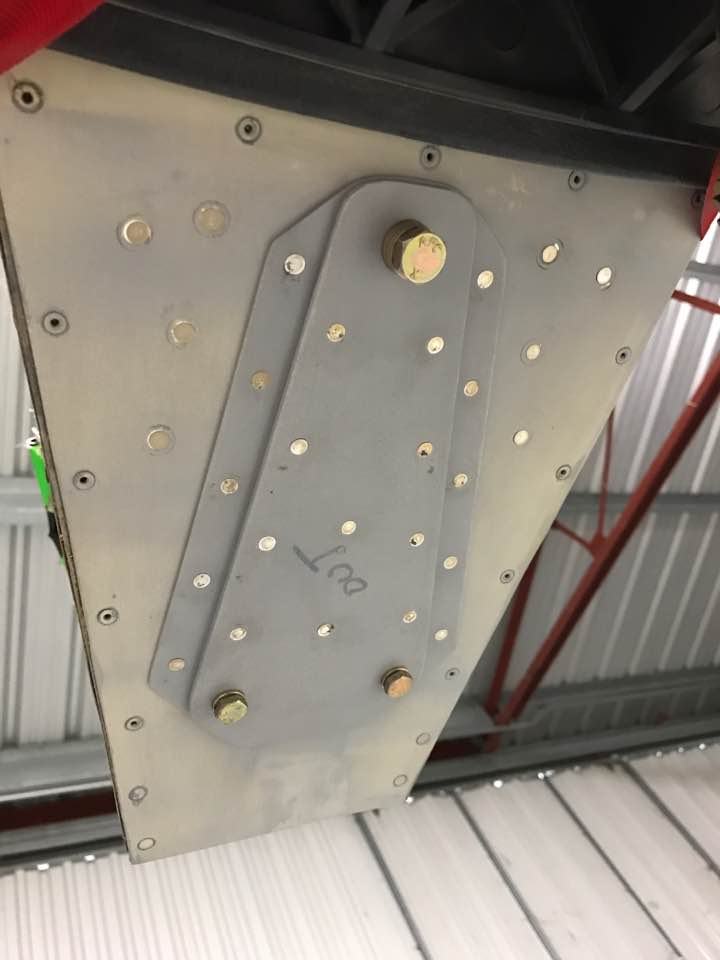
Skeeter had planned to use clear tubing in the cockpit as a fuel level sight gauge. I decided not to pursue that option. In the end, I think it would be awkward and more complicated to install (given my panel design). I verified that I can use a resistance type fuel sensor in the tank with the Skyview system I plan to install. That means I'll need to install an access panel in the top of the tank so I can mount the sensor. I want to be able to easily remove/replace the sensor in the future for maintenance, so I also need to install an access panel on the top of the fuselage. This is a bit tricky because there is limited space between the frames on the upper skin. This access panel doubler must be just under 5 inches in width and allow room to remove the sensor bolts and sensor itself from the tank. I designed/fabricated the doubler from 0.032 sheet and a template for the cover from 0.062 sheet, match drilled the holes through the bottom of the skin, and scratched out the cover through the 0.025 skin. I used thicker stock for the cover template because it helps to keep the awl from slipping off the template when scratching out the cover. I've done this several times for different panels and it works well as long as the skin is 0.032 thick or less. Once I had the cover scratched out, I finished the edges, drilled out the attachment holes, dimpled them, installed #8 nut plates in the doubler, primed the mating surfaces, riveted the doubler in place, and installed the cover. This took some time, but the result is worth the effort.

I continued working on the instrument wiring through the firewall. I drilled attachment holes through the firewall for the manifold pressure sensor and Dan Jansen came over to help me attach the ammeter shunt to the firewall and replace the lower cowl to check clearance for the exhaust temperature probes. I also fabricated a bracket to mount the oil pressure sensor to the firewall. I replaced the fuel tank in the fuselage to locate the fuel sensor cutout below the access panel in the fuselage. I marked the location on the tank and brought it back home to work on that cutout.
Apr 2019
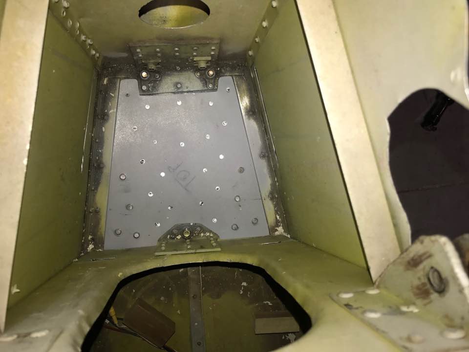
I designed the access panel doubler for the fuel tank and fabricated the doubler and template for the cutout from 0.040 sheet. I also started fabricating the cover from 0.032 sheet. I am using two rows of attachment holes in the doubler to provide more attachment area for the proseal and hopefully prevent any fuel leakage. This makes for a larger doubler, but I think it is necessary. The cover opening is 2.875 inches wide to accommodate the attachment ring for the fuel level sensor. Also, the doubler must be oval since it must be installed from the outside of the tank. The overall tank doubler dimensions are approximately 9.5 x 7 inches.


May 2019
I continued to work on the fuel tank modification for the fuel sender. I also finished work on the fuel door for the upper fuselage skin. I added an inside doubler to stiffen it and installed a quarter turn fastener system to secure it. The previous owner planned to use a spring loaded pin/latch system, but it will not work for my panel installation (no good way to route the release cable). It was also over complicated IMO. I installed supports for the Dynon EMS wiring inside the fuselage. I needed a way to secure the wiring and provide clearance with the fuel tank. I also installed the EGT probes in the exhaust stacks.


Jun 2019
I had to design a few tools to align the outboard wings. The previous owner had fabricated new outboard wings and the rear spars had not been match drilled to the center wing. I had to find a way to hold the wing in place while match drilling the read spar attachment holes. I fabricated a tool to attach to the center wing and provide a way to hold the outboard wing in position for drilling. I also did not want to damage the existing attachment hole in the center wing rear spar, so I cut a piece of 1/4 inch steel tubing (the existing hole is 1/4 in.). To fit in the hole, I had to remove some material from the tube. The I.D. of the tube allows a 3/16 drill bit to be used to make a pilot hole in the outer wing rear spar. I used a 90 degree drill with a spring to ensure the tube was engaged in the 1/4 inch hole so that the new pilot hole was exactly centered and no damage was caused in the existing hole. To align the wings, I clamped the trailing edge of the flap (fully up) to the training edge of the aileron. Then, I carefully checked to ensure that the aileron was in the neutral position and the inner/outer wings were lined up. I did several checks. :-)


Dan Jansen helped me remove the center wing again so we could fill some old fairing attachment holes in the fuselage (had been covered by the nose ribs). I will start working on attaching the cowling to the fairing and fuselage.

July 2019
I replaced the engine cowling to start working on new attachment holes on the forward fuselage. Since the engine has moved slightly with the new mount and vibration isolators, I had to make adjustments to the fiberglass fairing and this changes the way the cowling will mount to the fuselage. The next job will be to make new landing gear fairing cuffs that also mount to the lower part of the fairing.

Aug - Sep 2019
Started working on the gear fairing cuffs. Since the cowling moved, the old cuffs don't fit. I have to make a new set.


I laid-up each half on both sides using some scrap aluminum sheet as a male mold and covered the area with clear packing tape. I used dacron tape to help keep the surface as smooth as possible. Still plenty of sanding and filling...

I did some preliminary trimming and checked the fit again.
Nov - Dec 2019
Continued working on the engine wiring and fuel tank installation.

I also worked on the center console and how to run fuel to a decent shut-off valve and Facet boost pump.
Jan - Feb 2020
Continued working on the shut-off valve installation. Also bled the brake lines and filled the master cylinders.

I installed a temporary partial panel to allow me to make sure the engine will start. If I have to do more work on the engine, I don't want to spend money on the Dynon glass panels for them to simply sit on the shelf until the engine is ready to go.

Mar - May 2020
I installed/timed the mags, and I'm happy to say that the engine ran well. I found a few minor oil leaks, but nothing major. I then started working on a mounting point for the Dynon ADAHRS. The best location is under the deck behind the seats and above the baggage area. I fabricated two stiffeners to run under the deck between the BHs on either side of the ADAHRS and one running between the longitudinal stiffeners just aft of the ADAHRS. I designed/fabricated the mount to hold a primary and secondary ADAHRS using the Dynon mounting plate. I riveted one of the mounting plates to the base of the mount. I designed the base to be removable with SS machine screws so that I can remove the ADAHRS when necessary. I also attached a tab on the left longitudinal stiffener with rubber grommets for the air lines. I riveted everything in place on the deck.
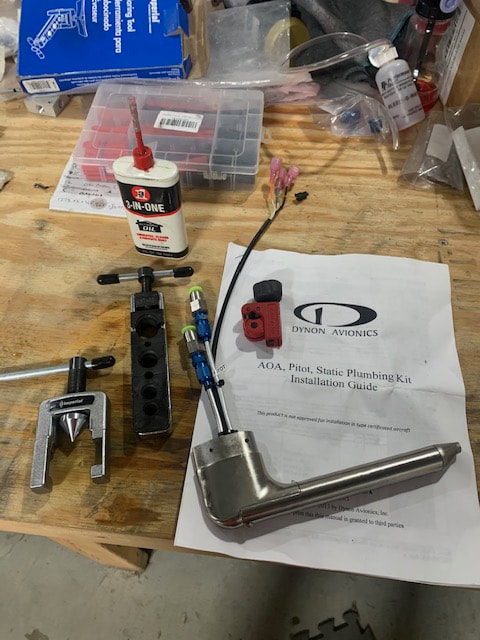
I cut/flared the pitot and AOA tubes on my Dynon heated pitot. I had installed the pitot boom some time ago and now it's time to install the tube in the boom with the air lines. I cut the lines in a staggered pattern to allow me to insert it in the boom easily. I was a little concerned about screwing up the process, but it all went well. Measure twice, cut once :-)
I ran the air lines through the left wings (center and outer). It was a bit of a challenge running the lines through the center bay without an access panel, but I used a 1/4 inch push/pull cable to feed through the bay and taped the lines to the cable to pull them through the bay.


I cut a finger from a nitrile glove to cover the pitot tube until I can find a nice cover. I then ran the air lines back to the ADAHRS mount under the pilot seat.
Jun - Oct 2020
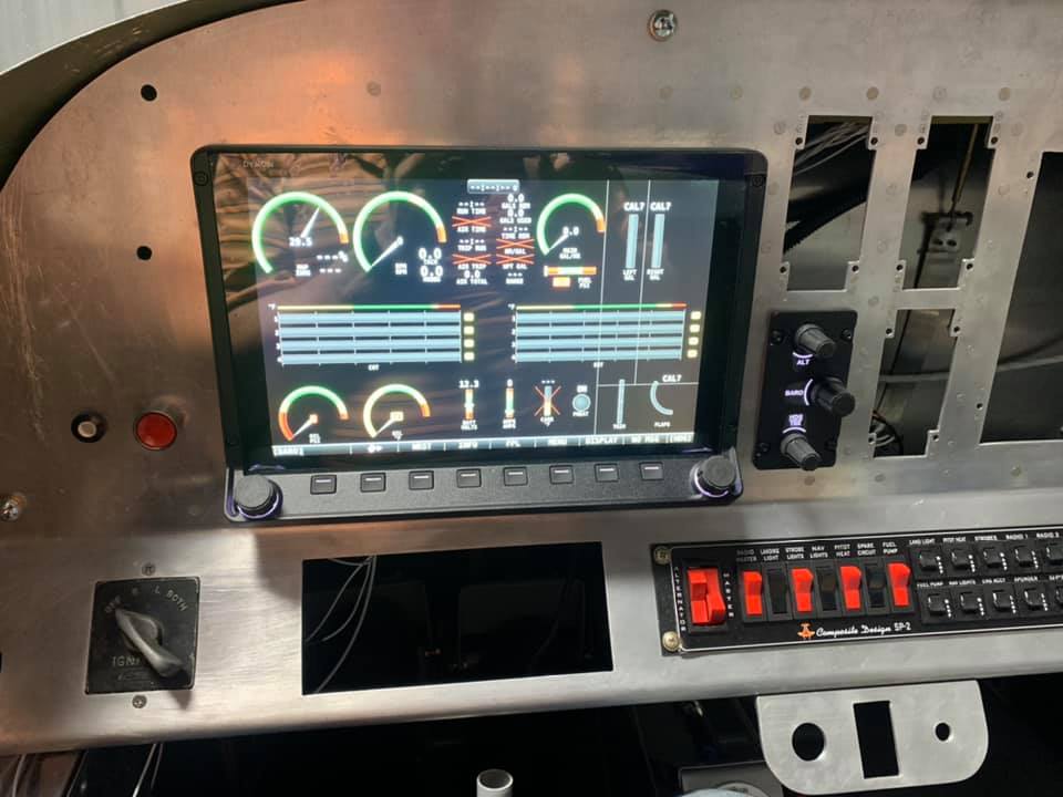
Ran the pitot and electric wiring from the wing tips to the fuselage. Connected the wiring to the power panel and labeled the wires at the panel. Temporarily connected the mixture control to the panel, finished the flap wiring and installed the flap toggle switch in the panel. Also installed the first Dynon screen, Knob control, and connected the EMS computer.
Nov - Dec 2020
Trimmed and installed the wing tips. I installed #8 nut plates to secure the tips.

Jan 2021
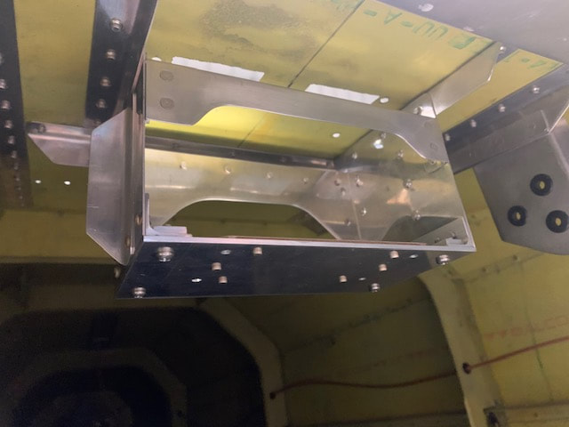
Installed the Dynon network hub and fitted a new mounting BH under both seats. These will be useful for additional capability for avionics and storage (e.g. oil, tools, etc.).

Riveted the under seat mounting BHs
Feb - Mar 2021
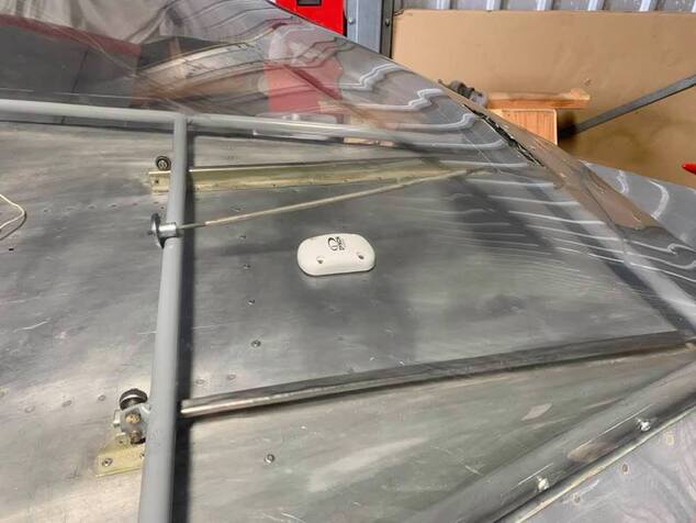
Fabricated network cables to connect the ADAHRS and autopilot servos to the Dynon network. Ran the cables to the network hub from the ADAHRS and Display. Everything worked like a charm. I then installed the outside air temperature probe on the bottom of the left wing near the access panel near the wing root and ran the wires back to the ADAHRS. I needed to test the GPS antenna location on the top of the turtle deck (under the canopy) to be sure it would work without interference.

Rolled the airplane out of the hangar to run the engine and see how the antenna location worked


Apr 2021
Spent some time working on the Dynon GPS antenna installation. I fabricated stiffeners to support the antenna under the turtledeck and Dan Jansen came over to the airport to help me rivet the stiffeners. It looks a little messy because I used proseal between the stiffeners and the skin.
The clearance between the canopy structure and the antenna is just under 1/8 inch as you open and close the canopy. It works.
I secured the antenna wires and temporarily connected them to the Dynon display. I will need to make a permanent connection once I install the second display. For now, it is good enough to allow me to be sure that everything is working.
May - Sep 2021

A lot of finishing work over the last few months. I spent a lot of time fabricating and installing the fairings for the inboard/outboard wings. Also, I reamed the outer wing attachment holes for new NAS bolts. Then, I fabricated and installed the canopy trim. Finally, I replaced the fuel flow sensor and the mixture cable. I took it out to run the engine and everything worked well. It's getting closer!
Oct 2021
I've been working on the gear leg cuff fairings this month. I replaced the forward cowling and started work fitting my fiberglass cuffs. I also epoxied dimpled washers on the cowling attachment holes to help prevent wear on the fiberglass holes and allow me to use C/S machine screws on the cowling.


I also made good use of a "new" tool a friend (Joe Kilpatrick) gave me to back drill some attachment holes through the fiberglass cuffs.
Nov - Dec 2021

Continued to work on the gear leg cuffs. I installed rivet nuts in the fuselage to attach the aft portion of the cuffs to the airframe and installed 4 additional nut plates on the bottom skin to attach the cuffs to the bottom of the air frame. My son, Justin helped me rivet the nut plates on the bottom skin. The rivet nuts worked on the side of the fuselage because of the fiberglass fairing provides a stand-off from the skin. I simply had to cut clearance holes in the fiberglass to accommodate the rivet nuts. I used existing nut plates in the fiberglass cowling. I then located the hole locations in the fiberglass cuffs using a flashlight inside the air frame since the fiberglass is translucent. I had to use LED lights inside of the gear leg fairings since I could run the wires between the cuffs and the fairings (no way to get a flashlight in there with the cuffs in place). Finally, I painted the cuffs with epoxy based paint and reinstalled them on the airplane.
May 2022

Installing autopilot servo for roll control
Jun 2022 - June 2023

Well, it's been a minute ;-) since my last update. I'll attach a few pictures below to get caught up. To summarize, I finished installing the autopilot servos last year. The pitch servo installation was a bit complicated. I decided to install the servo next to the roll servo under the co-pilot seat and run a push rod to the control stick bracket. It worked out well, but it requires a cover to protect it from anything than could fall under the seat and jam the control.

Then, I verified that the engine had no provision for a mechanical fuel pump, so I installed an electric pump, added a panel switch, and wired it directly to the battery. A pump is required to give me sufficient fuel flow, and this pump will be the main and I wanted to protect it in case the master solenoid ever failed in flight. The backup pump runs off the fuel pump switch on my main power panel.
The next major project was figuring out how to install stick boots and include a cover for the a/p pitch control.


This also included wiring the pilot stick grip for trim, a/p disconnect, and the PTT switch.
Installed a piece of 3/4 aluminum angle stock to support the canopy vent control. It works by tightening and loosening the threaded knob attached to the control rod.


I installed the Dynon remote radio, belly antenna, audio panel, and com panel. This included building the wiring harnesses and running the wiring. I also installed the headset plugs on the bulkhead behind the seats to keep the wires out of the way. I allowed for a little extra wire - just in case there would be a need to rework the wiring later. Better to have a longer wire run than have to re-run it all again.
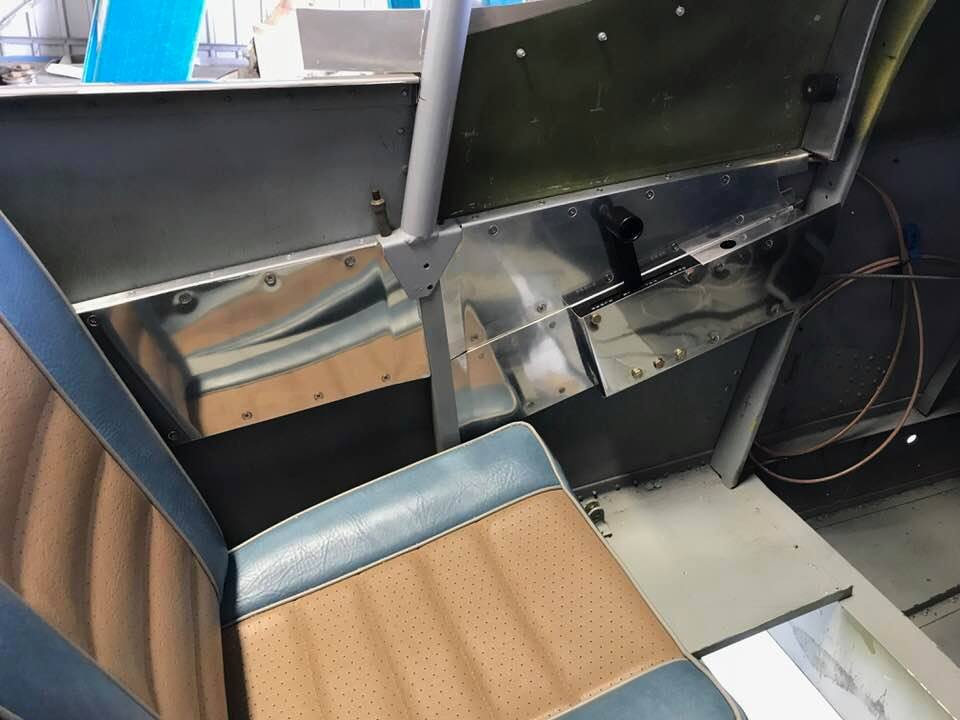
The canopy needed to be raised to reduce the gap between the windshield skirt and the canopy skirt. I decided the best way to proceed was to drill out the side rails and raise the rails by adding skin splices that rotated the rails from the back attachment so that the front of the rail would be approx. 5/16 higher to help to close the gap.

I fabricated instrument panel covers for the co-pilot EFIS panel and the cut-outs for the IFR GPS and transponder on the lower portion of the IP. I am waiting until I have flown the airplane for a while to work out any problems and spread out the cost of the second Dynon HDX display as well as the expensive GPS. I have decided to go with a remote transponder and ADSB. These can also wait until I've flown since I can stay out of the CVG Mode C veil for now.
I didn't want to drill any holes in the IP around the lower panel cut-outs until I know exactly what I want to do with these openings. I have sized the pilot side for either a Garmin 430 or Avidyne 440, but until I have the rack, I don't want to add any other attachment holes. So, I riveted a 0.090 thick (same as the IP) frame on the inside of the covers and installed nut plates on backing plates to secure the covers. I had an additional issue with the Dynon battery backup. It needs to be close to the display because Dynon doesn't approve lengthening the wiring. If/when I install the GPS, I'll be able to attach it to the top or side of the mounting rack, but for now I rigged up a temporary attachment to the inside of the cover. After installation, I charged the battery by connecting a charger to the airplane battery and turned on the HDX display. The system has a diagnostic screen to display the battery status. After it was fully charged, I turned off the HDX and the system notified me that power was lost and asked about shutdown - worked perfectly. :-)
I didn't want to drill any holes in the IP around the lower panel cut-outs until I know exactly what I want to do with these openings. I have sized the pilot side for either a Garmin 430 or Avidyne 440, but until I have the rack, I don't want to add any other attachment holes. So, I riveted a 0.090 thick (same as the IP) frame on the inside of the covers and installed nut plates on backing plates to secure the covers. I had an additional issue with the Dynon battery backup. It needs to be close to the display because Dynon doesn't approve lengthening the wiring. If/when I install the GPS, I'll be able to attach it to the top or side of the mounting rack, but for now I rigged up a temporary attachment to the inside of the cover. After installation, I charged the battery by connecting a charger to the airplane battery and turned on the HDX display. The system has a diagnostic screen to display the battery status. After it was fully charged, I turned off the HDX and the system notified me that power was lost and asked about shutdown - worked perfectly. :-)
July 2023
Working on the fresh air intake. The canopy can't be opened in flight and there was no good way to add an alternate air intake to the canopy. This will allow cooling on the ground and air and allow fresh air to flow through the cockpit. I had already installed a 2-inch butterfly valve pass-through on the firewall, so I just need to fabricate a NACA duct on the bottom cowl to run a SKEET hose to the valve and run the control cable to the valve on the co-pilot side.
I bought a polycarbonate NACA scoop from Aircraft Spruce, but that probably won't work well in the potentially warm/hot engine compartment. It was made to be installed on the fuselage, so I used it as a mold for a fiberglass scoop that I can cover with heat reflective tape as part of a larger vent system that will expand the incoming air to a 2-inch flange for the SKEET hose.
I bought a polycarbonate NACA scoop from Aircraft Spruce, but that probably won't work well in the potentially warm/hot engine compartment. It was made to be installed on the fuselage, so I used it as a mold for a fiberglass scoop that I can cover with heat reflective tape as part of a larger vent system that will expand the incoming air to a 2-inch flange for the SKEET hose.


Aug 2023 (Finally Ready to Fly!)
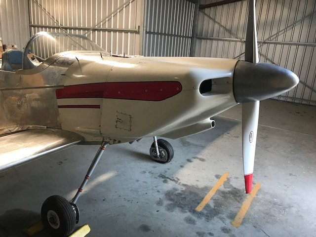
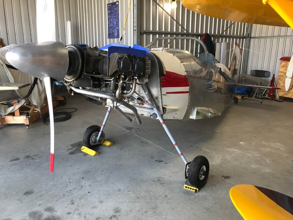
The fresh air vent was the last major item I wanted to finish before preparing to fly the T-18 (Kuzco). I finished the vent this month and scheduled time with my good friend, Jasson, to check and document the weight and balance for Kuzco. I fabricated a small stand to level the airplane and Jasson came to my hangar to weigh Kuzco. I was very suprised and happy to find that Kuzco weighed only 915 lbs empty. My son, Sean Roarty, flew up from N. Carolina to check over the airplane on Aug 16. Sean is an IA and he gave Kuzco a complete inspection from tail to spinner and made a few adjustments and changes. Once completed, we were ready to fly on Aug 19th. My brother (Bill) drove over from Indianapolis to visit us and watch the flight. It was great having Sean in the right seat next to me helping to monitor the instruments while I flew. The #4 cylinder got hot during the climb, but pulling power back did the trick. I will have to do a little more work on the engine baffling. In any case, the first landing was a bit nose high and I touched the tail wheel first. Other than that slight error, everything went well. Kuzco flys nicely - very solid and easy to control. I flew Kuzco a few more times this month. I calibrated the Dynon AOA sensor and worked on my pattern, approach, and landing speeds. So far, things are looking great. :-)
It took over 6 years for me to get to this point and it feels great to have it in airworthy condition.
Sep-Oct 2023
Continued testing the airplane and making adjustments here and there. I replaced one of the control rod bearings for the right aileron. As I was making some adjustments, the bearing came apart when I was trying to loosen the jam nut. I also did a lot of work on the engine baffle seals and added some baffling to block air at the bottom of the front cylinders to force more air up over the cylinders to help cool the rear cylinders. I also blocked off a major portion of the oil cooler mounted behind cylinder #4. These changes made a big improvement in the CHTs for #3 and #4. Now, the temps run around 258-265 in the back and around 200-210 in the front. I also spent more time polishing the aluminum. I used Flitz, but I'm going to need to do it again at a later date with a polish with some fine grit to help remove the scratches from the paint removal process. Finally, I received the b-nut I ordered from Aircraft Spruce to allow me to connect the fresh air vent butterfly valve to the control cable. That was a big job and tool me ~7 hours total time to complete. The problem was the fact that the fuel tank is just above the valve and there is no good way to reach the valve from the cockpit. I had to reach through one of my access panels on the bottom skin (thank God I added those to service the brakes. Anyway, I had to use one hand to place the b-nut on the valve arm and used a strip of painters tape to provide a tight fit so it wouldn't fall out. It fell out anyway - several times. I then used some dental floss to help me retrieve the nut when it dropped out. After several attempts, I managed to get a washer and cotter pin on the nut. Then, I had to fish the control cable through the nut and tighten the allen nut to secure it.
Nov 2023
New Cato 3-blade prop!

I also had the new prop dynamically balanced by Neal Tudor. Next, I installed a Dynon remote transponder (SV-XPNDR-261) and ADS-B reciever (SV-ADSB-472) in the airplane, installed the two antennas on the belly, and ran the RG-400 coax.
Dec 2023
I flew several local flights to check out the ADS-B equipment. I discovered that it helps to read the Dynon manual before configuring the transponder ;-). Once I got that figured out, things appeared to be working. I flew a test flight to get my FAA Public ADS-B Performance Report and passed everything. Now, big brother can watch me at all times.

Jan 2024
Got my biennial transponder check done by Jasson so I'm now legal to fly in ADS-B areas. This frees me up to start expanding my flights. So far, the weather here has been terrible and I've only flown once (Jan 4). Hope to fix that soon.